

How to Choose the Right Ferrite Magnetic Ring?
Choosing the right Ferrite Magnetic Ring is a practical engineering decision, not a simple size comparison. These rings appear in power supplies, USB cables, automotive harnesses, and industrial control cabinets. Their main purpose is suppressing unwanted electromagnetic interference through increased impedance. The correct choice depends on frequency, current, cable geometry, material, and installation space.
Industry reports show why this decision matters. MarketsandMarkets’ electromagnetic compatibility research identifies rising electronic density as a major driver of interference-control demand. Grand View Research also reports continued growth in ferrite-based magnetic materials across electronics and power applications. However, broad market figures cannot select a core for a specific cable. Real performance still depends on measured impedance, winding turns, and operating temperature.
Start with the interference problem. A MnZn Ferrite Magnetic Ring usually suits lower-frequency noise and power applications. NiZn materials often perform better at higher frequencies. Check the manufacturer’s impedance curve, not only the nominal size. A ring may look ideal.
It may still saturate.
Measure the cable’s outside diameter and available clearance before ordering. Then compare the required impedance at the actual noise frequency. Consider current heating, mechanical vibration, insulation thickness, and repeated assembly. Fair-Rite, TDK, and Würth Elektronik datasheets provide useful frequency curves and material specifications. IEC 60404-8-1 also supports disciplined evaluation of magnetic material properties. One weakness in many buying guides is their focus on catalog values. Field measurements often reveal installation effects that laboratory tables cannot show. A clamp probe, spectrum analyzer, or conducted-emissions test can expose those differences. Careful selection combines report-based market awareness with datasheet evidence and application testing.
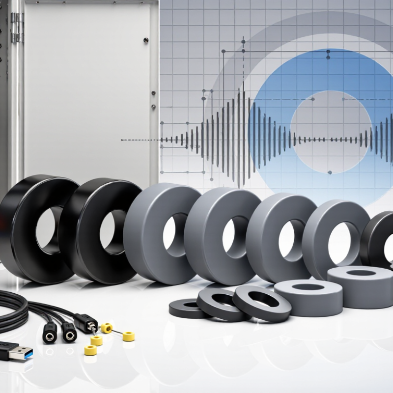
Classify Ferrite Type: MnZn for kHz–MHz and NiZn for 1–300 MHz
How to Choose the Right Ferrite Magnetic Ring?
Ferrite material determines how a magnetic ring behaves across frequency. MnZn ferrite is commonly selected for kHz to low-MHz applications. It offers high permeability and strong magnetic performance at lower frequencies. Designers often use it for power filtering, transformers, and switching-noise suppression. However, its performance can decline as frequency rises.
NiZn ferrite is better suited to approximately 1–300 MHz. It usually has higher resistivity and lower parasitic loss at radio frequencies. This makes it useful for signal filtering, cable suppression, and electromagnetic interference control. The exact range depends on the formulation, ring size, and operating temperature. A useful rule, not a law.
Tips: Check impedance at your actual frequency, not only the material label. Measure the ring with the intended number of turns. A small air gap, long lead, or nearby metal part can change results. Compare insertion loss and temperature rise during testing.
In practical projects, I have seen engineers choose MnZn because its permeability looked impressive on paper. The circuit still performed poorly at 20 MHz. The material was not necessarily defective. The operating frequency had simply moved beyond its efficient region. NiZn may work better there, but excessive turns can add unwanted capacitance. Keep the winding short and test several ring dimensions. Datasheets guide selection; measurements confirm it. Do not ignore mechanical fit, insulation, or temperature stability.
How to Choose the Right Ferrite Magnetic Ring? - Classify Ferrite Type: MnZn for kHz–MHz and NiZn for 1–300 MHz
| Selection Dimension | MnZn Ferrite Manganese-Zinc | NiZn Ferrite Nickel-Zinc |
|---|---|---|
| Typical useful frequency range | Commonly selected from several kHz through the lower-MHz region. Some formulations are optimized for operation up to a few MHz. | Commonly selected from approximately 1 MHz to 300 MHz, with suitable grades extending into the upper-VHF and lower-UHF region. |
| Recommended first choice | Choose MnZn when the design requires high inductance, strong impedance at lower frequencies, or energy storage in power magnetics. | Choose NiZn when high-frequency noise suppression, broadband impedance, or low parasitic capacitance is more important than maximum permeability. |
| Typical initial permeability, μi | Approximately 500 to 15,000, depending on grade, frequency, temperature, and measurement conditions. | Approximately 10 to 2,000, depending on grade and frequency. High-frequency grades generally use lower permeability. |
| Electrical resistivity | Typically about 1 to 100 Ω·m. Higher resistivity than metallic magnetic materials, but generally lower than NiZn. | Typically about 103 to 106 Ω·m, making NiZn suitable for reducing eddy-current loss at higher frequencies. |
| Saturation flux density at room temperature | Typically about 0.25 to 0.55 T, depending on composition and operating temperature. | Typically about 0.15 to 0.35 T, generally lower than MnZn for comparable operating conditions. |
| Relative loss behavior | Usually provides lower core loss than NiZn at many power frequencies and lower-MHz conditions, provided the selected grade is operated within its specified range. | Usually provides lower high-frequency eddy-current loss because of its much higher resistivity; magnetic loss still depends strongly on frequency, flux level, and grade. |
| Typical magnetic impedance behavior | High permeability produces strong impedance at lower frequencies, but impedance can decline rapidly as frequency approaches the material's resonance and loss region. | Lower permeability but effective impedance over a wider high-frequency range; useful for broadband suppression and radio-frequency interference control. |
| Common magnetic ring applications | Power inductors, transformers, common-mode chokes, differential-mode filters, switching-power supplies, and low-frequency EMI filters. | High-frequency EMI suppression, RF chokes, signal-line filters, antenna circuits, coaxial cable suppression, and broadband common-mode noise reduction. |
| Temperature capability | Curie temperatures are commonly around 200–300°C, but usable operating temperature is limited by the specific grade, loss, insulation, and application conditions. | Curie temperatures are commonly around 150–500°C across different formulations; the specified operating temperature must be confirmed for the selected grade. |
| Main design trade-off | Higher permeability and saturation capability, but greater parasitic capacitance and lower suitability for very-high-frequency operation. | Higher resistivity and better high-frequency performance, but lower permeability and generally lower saturation flux density. |
| How to select the ring size | Select the core cross-sectional area and magnetic path length to meet inductance, current, temperature-rise, and saturation requirements. Check the manufacturer's AL value or effective magnetic parameters. | Select the size according to the required impedance, cable or conductor diameter, target frequency band, and available turns. For broadband suppression, verify impedance versus frequency rather than relying only on nominal permeability. |
| Critical verification tests | Measure inductance or impedance at the actual operating frequency, check DC bias or peak flux, evaluate temperature rise, and confirm core loss under the intended waveform. | Measure impedance across the complete frequency band, check the effect of winding capacitance, verify insertion loss or common-mode attenuation, and test the actual cable or circuit assembly. |
| Quick decision rule | If the main requirement is high inductance or magnetic energy handling from kHz to the lower-MHz range, start with MnZn. | If the main requirement is suppression from about 1 MHz to 300 MHz, especially on signal or cable assemblies, start with NiZn. |